
Electrical
Ignition & Main Switch Overhaul
- Neville
-
 Topic Author
- Offline
- Sustaining Member
-

- Posts: 90
- Thanks: 78
Ignition & Main Switch Overhaul
9 years 7 months ago - 9 years 7 months ago
After 37 years, both the main and ignition switches on my Z1300 A1 were showing significant voltage drops - particularly with the lights switched on (about 1.5 volts in total) - this was causing issues with the stator and regulator as the reference voltage feed to the regulator was lower than it should have been, apparently generating too much current through the stator windings causing several burn outs. What follows is my attempt to disassemble and clean the switches.
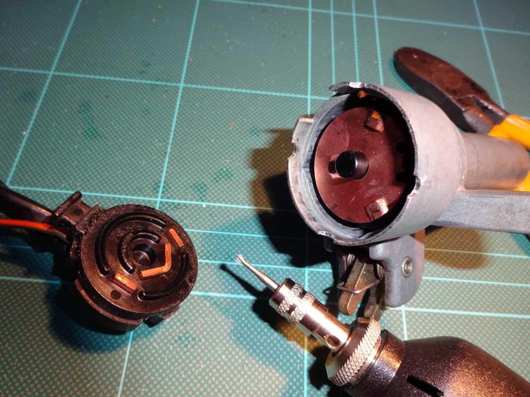
Ignition switch: First challenge is to prize this apart once you have removed it from the top steering yoke. The cover was relatively easy but I used a couple of small flat blade watchmaking screwdrivers inserted between the main housing and the main contact plate (centre and left respectively in picture below). After 37 years, the plastic housing can be brittle so this requires some care and patience! The deposits and wear on the main contact plate are fairly clear in the photo.
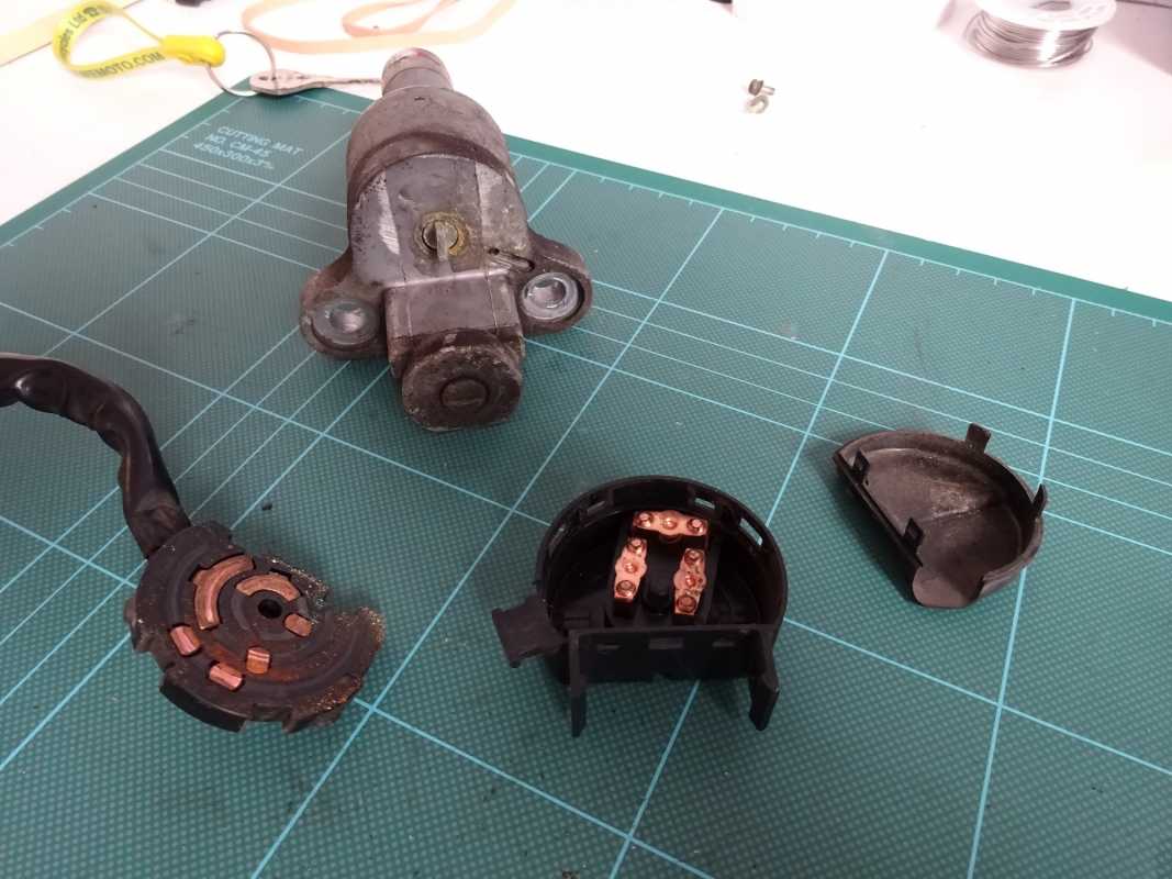
Also worth pointing out that the rotor arm and its sprung loaded contacts includes a small ball bearing under one of the springs which locates the rotor arm in one of four positions in the housing - mine had gone rusty and got stuck.
Next step was to clean up the main contact plate with 1200 wet and dry, clean up the rotor arm and the springs/ball bearing and reassembly - reassembly is much easier than disassembly! Switch now showing immeasurable resistance on my digital multimeter.
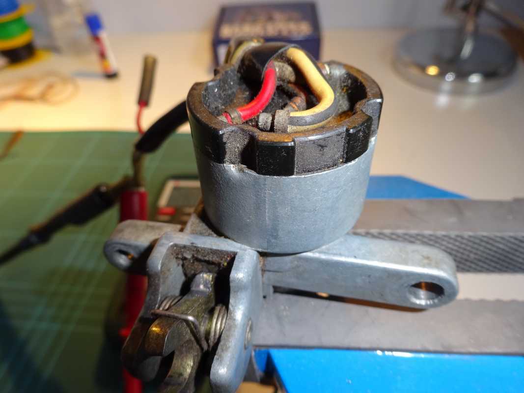
Main Switch: This was showing variable resistance on my multimeter and needed some care and attention - see picture below
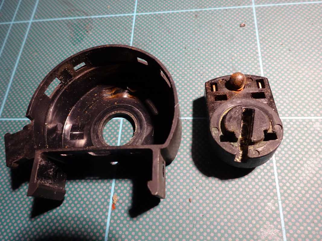
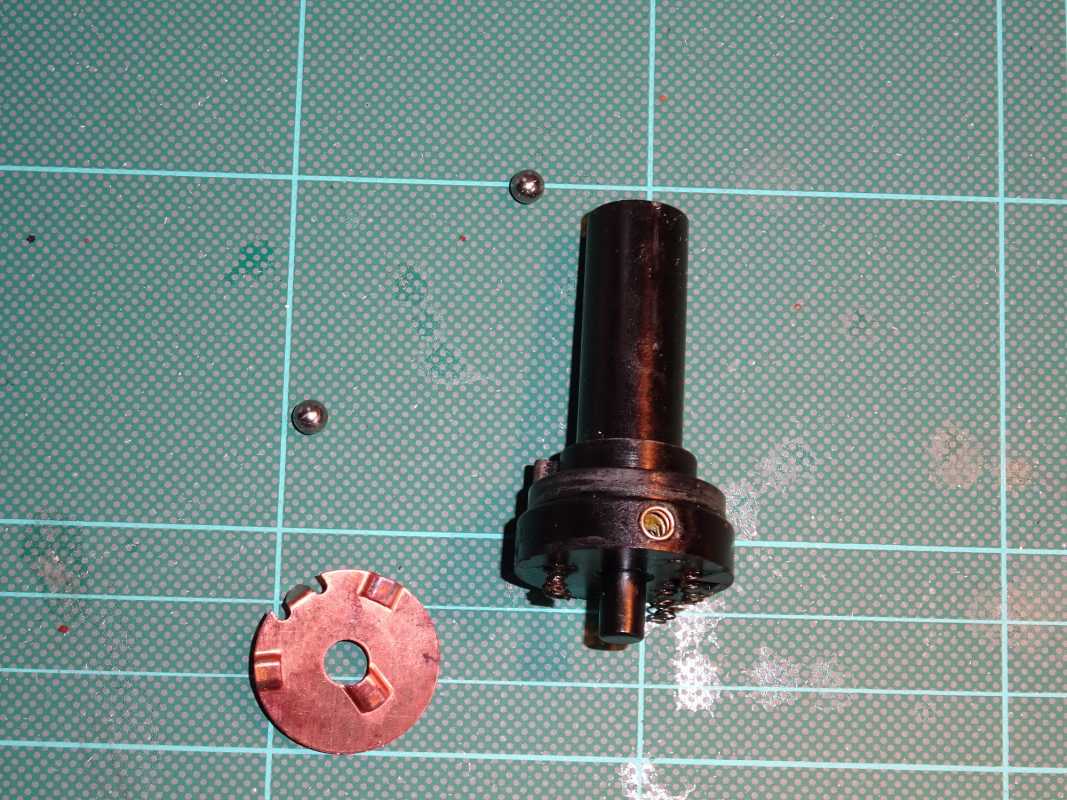
The first challenge in pulling this apart is that it is held together through 4 crimped areas in the metal part of the housing - trying to uncramp these is just not viable as it would break the rather brittle plastic part of the switch.
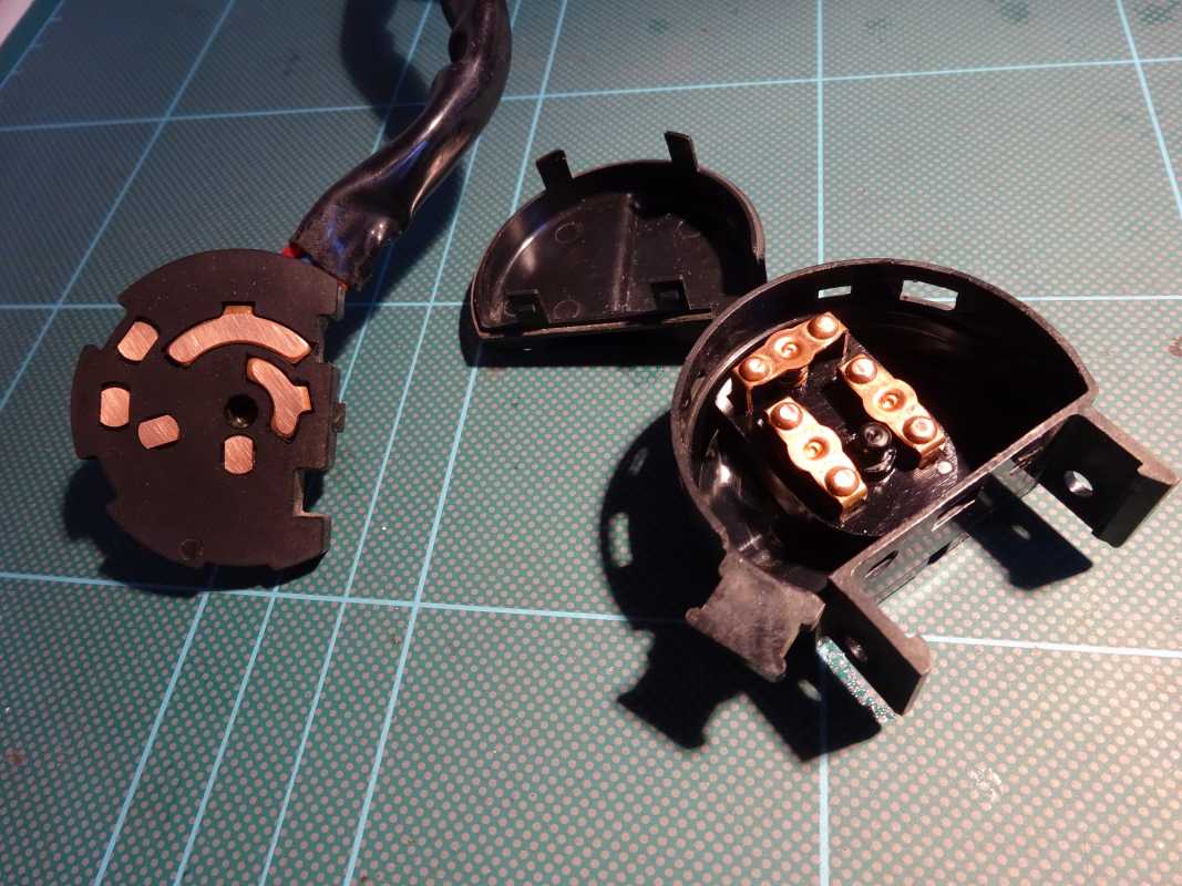
I used a Dremel type grinding bit to remove the crimped areas and then the plastic parts just pull out.
The inner part of the electrical switch includes a rotor arm with two ball bearings that locate the switch in a number of positions - these will spring out and you will lose them if you are not careful when you pull the rotor out.
Having ground away the crimped areas, I drilled some holes through the metal housing into the plastic part of the switch and inserted some screw fixings - very important to ensure your screw outer diameter and drilling diameter are pretty close or you will split the plastic housing (I found this out the hard way with my first attempt).
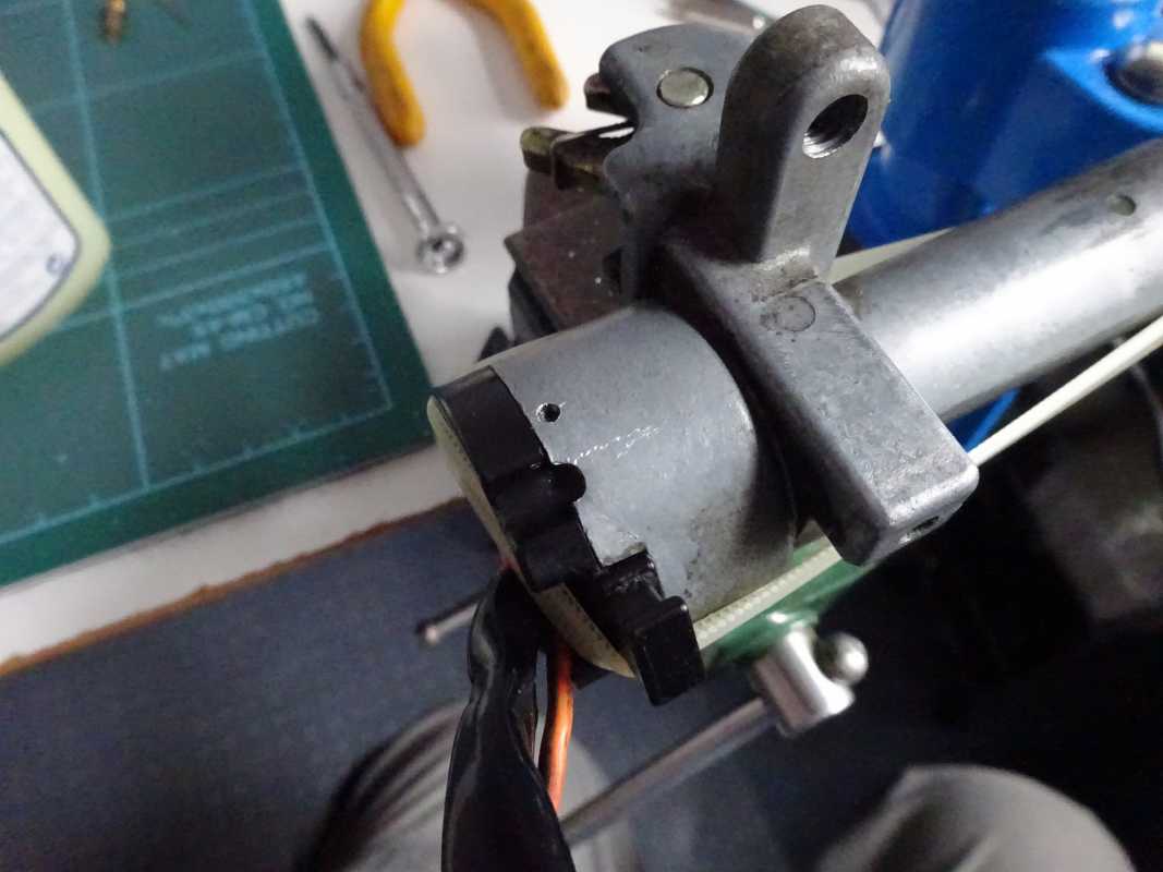
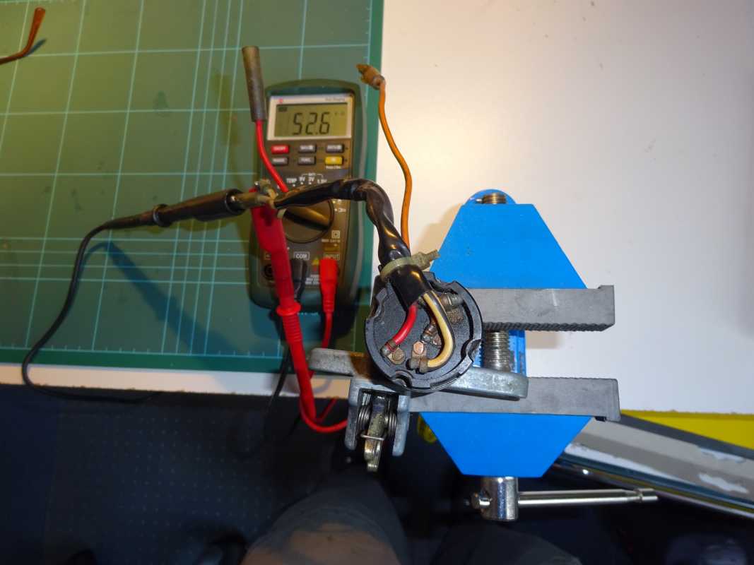
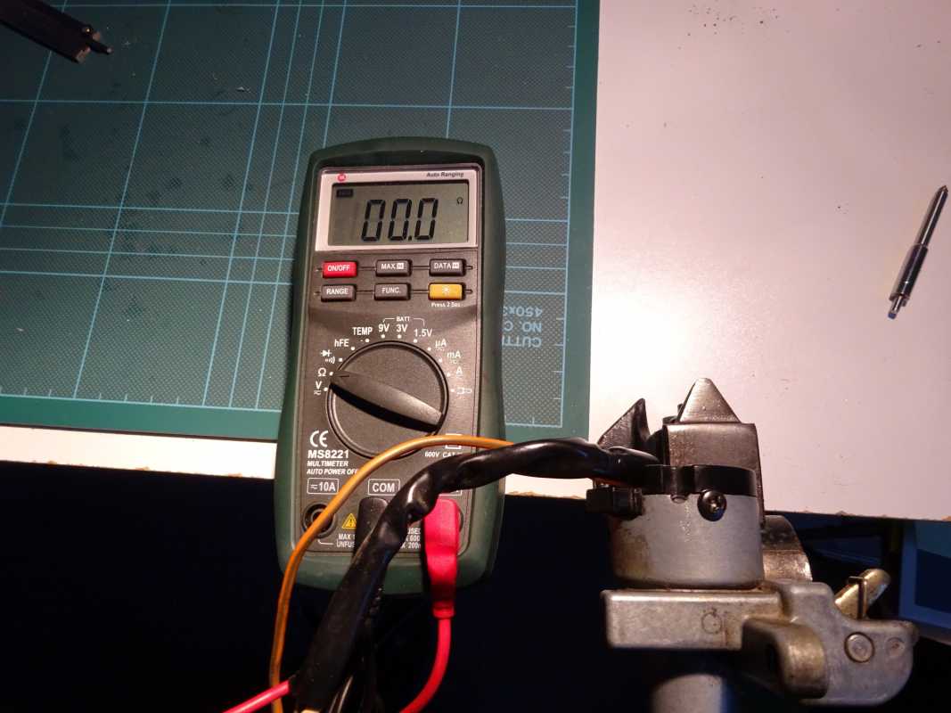
Final pic shows the reassembled switch, screw fixing (I used two, one each side) and resulting resistance measurement
Good luck!
Ignition switch: First challenge is to prize this apart once you have removed it from the top steering yoke. The cover was relatively easy but I used a couple of small flat blade watchmaking screwdrivers inserted between the main housing and the main contact plate (centre and left respectively in picture below). After 37 years, the plastic housing can be brittle so this requires some care and patience! The deposits and wear on the main contact plate are fairly clear in the photo.
Also worth pointing out that the rotor arm and its sprung loaded contacts includes a small ball bearing under one of the springs which locates the rotor arm in one of four positions in the housing - mine had gone rusty and got stuck.
Next step was to clean up the main contact plate with 1200 wet and dry, clean up the rotor arm and the springs/ball bearing and reassembly - reassembly is much easier than disassembly! Switch now showing immeasurable resistance on my digital multimeter.
Main Switch: This was showing variable resistance on my multimeter and needed some care and attention - see picture below
The first challenge in pulling this apart is that it is held together through 4 crimped areas in the metal part of the housing - trying to uncramp these is just not viable as it would break the rather brittle plastic part of the switch.
I used a Dremel type grinding bit to remove the crimped areas and then the plastic parts just pull out.
The inner part of the electrical switch includes a rotor arm with two ball bearings that locate the switch in a number of positions - these will spring out and you will lose them if you are not careful when you pull the rotor out.
Having ground away the crimped areas, I drilled some holes through the metal housing into the plastic part of the switch and inserted some screw fixings - very important to ensure your screw outer diameter and drilling diameter are pretty close or you will split the plastic housing (I found this out the hard way with my first attempt).
Final pic shows the reassembled switch, screw fixing (I used two, one each side) and resulting resistance measurement
Good luck!
Last edit: 9 years 7 months ago by Neville. Reason: Add an extra picture
The following user(s) said Thank You: Bucko, McZed, Kawboy, globemaster
Please Log in or Create an account to join the conversation.
- Kawboy
-

- Offline
- Sustaining Member
-
- Posts: 3248
- Thanks: 1203
Re: Ignition & Main Switch Overhaul
9 years 7 months ago
Great write up !! Love the detail.Nicely done.
Just a little detail some of you might be interested in - When drilling plastic, it can be difficult to drill without cracking the material. The problem is that the drill bit wants to pull itself through the material because the leading edge of the drill bit is very sharp like a chisel and digs in too much. The trick for drilling plastic and soft material is to take a honing stone and flatten off the chisel face just enough so you can see a small flat spot on the leading edge. That will stop the drill bit from pulling itself through the material faster than it needs to go through. This is a practice taught to millwrights in their apprenticeship. Good to know.
My 2 cents.
The following user(s) said Thank You: Neville
Please Log in or Create an account to join the conversation.
- stocktoy
-

- Offline
- Sustaining Member
-
- Posts: 381
- Thanks: 90
Re: Ignition & Main Switch Overhaul
9 years 7 months ago
Wow great write up. I've never had the :woohoo: to take apart the switches just in case my luck held true and I'd be looking for new ones.
Now I've seen it done if need be I'll try too.")
Thanks
Now I've seen it done if need be I'll try too.
Thanks
The following user(s) said Thank You: Neville
Please Log in or Create an account to join the conversation.
- globemaster
-
- Offline
- Sustaining Member
-
- Posts: 127
- Thanks: 57
Re: Ignition & Main Switch Overhaul
9 years 7 months ago
Outstanding work and exceptionally concise photographs with the detailed procedure. This will probably help countless 1300 owners solve myriad problems caused by voltage drops in the main and ignition switches.
Please Log in or Create an account to join the conversation.
- Ledkz1300
-

- Offline
- Platinum Member
-

- Posts: 627
- Thanks: 71
Please Log in or Create an account to join the conversation.
- scotch
-

- Offline
- Sustaining Member
-
- Posts: 2033
- Thanks: 938
Re: Ignition & Main Switch Overhaul
9 years 7 months ago
Well done !
1980 KZ 1300 sr# KZT30A-009997
Always High - Know Fear !
Always High - Know Fear !
Please Log in or Create an account to join the conversation.
Moderators: scotch
Time to create page: 0.176 seconds